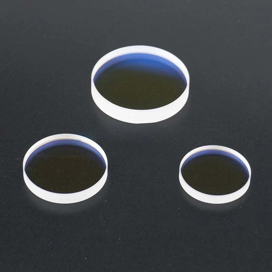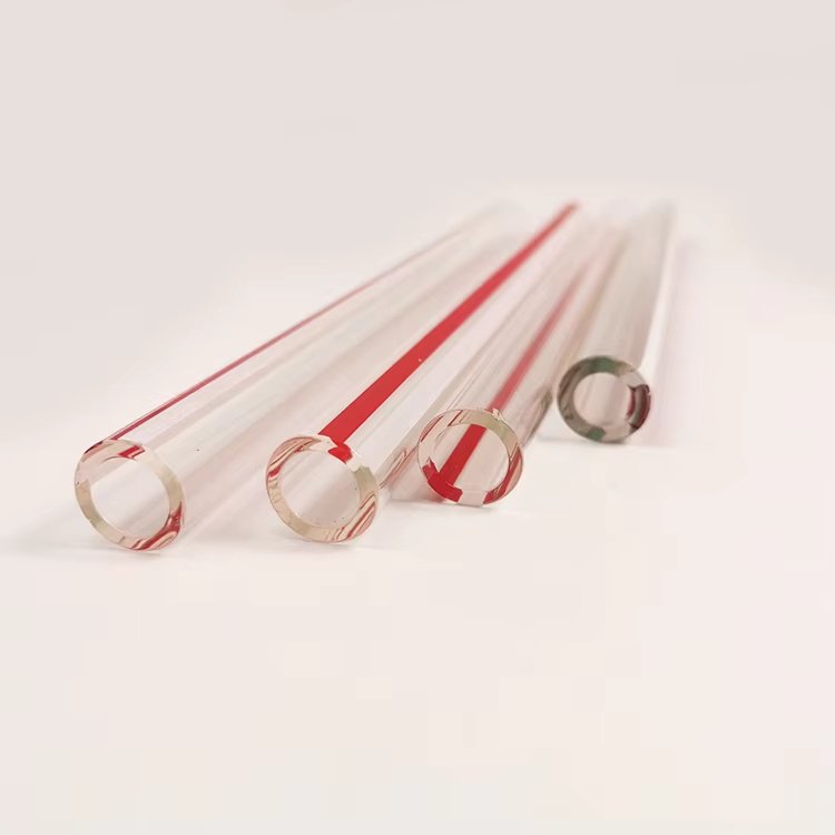
A fiber laser quartz end cap is a short coreless fused-silica element fusion-spliced to the delivery fiber. Its main job is to let the guided beam expand before it reaches the air-glass interface, reducing optical power density at the exposed surface and protecting the fiber end.
The component is simple in appearance but unforgiving in execution. Diameter, length, material match, splice-face preparation, output-face angle, polish, coating and contamination control all interact with beam quality and damage resistance.
Quick answer: Choose end-cap length from the required beam expansion and available package, match the splice end to the fiber/cladding geometry, and define the output face by angle, polish, coating band and clear aperture. Treat cleaning and final inspection as part of the optical specification, not packaging notes.
Key Takeaways
- A coreless end cap lowers surface power density by allowing the beam to expand beyond the fiber core.
- Splice quality and material compatibility determine loss, residual stress and long-term reliability.
- A perpendicular output face and an angled output face solve different back-reflection and packaging problems.
- Surface defects and contamination can dominate laser-induced damage at high power.
- Power, wavelength, beam parameters and cooling/mounting must accompany dimensions in the RFQ.
Why Add an End Cap to a High-Power Fiber?
Without an end cap, the guided mode reaches an exposed surface while still confined to a small core area. Absorbing contamination, coating defects or microscopic damage at that interface can heat rapidly. A coreless fused-silica section allows diffraction and propagation to increase beam area before the beam exits.
The end cap can also provide a larger mechanical surface for polishing, coating and mounting. It does not eliminate all damage mechanisms: poor splice quality, cladding light, back reflection, contamination and insufficient thermal management can still limit the system.
Geometry: Diameter, Length and Concentricity
Outside diameter must support handling and package fit while remaining compatible with the splicing equipment. Length sets propagation distance and output beam size, but also affects alignment sensitivity, mechanical leverage and available housing space. Longer is not automatically better.
Concentricity between fiber, splice and end-cap OD matters when the housing locates from the cylindrical surface. If the optical alignment is established actively, a different datum strategy may be acceptable. State whether OD is a true optical datum or simply a protective envelope.
| Parameter | Optical/mechanical role | What to state |
|---|---|---|
| End-cap OD | Mounting, handling and splicer compatibility | Nominal, tolerance, roundness and datum use |
| Length | Beam expansion and package envelope | Finished length and reference faces |
| Splice-face angle | Fusion interface quality | Normally matched to splicing process |
| Output-face angle | Back reflection and beam steering | Angle, clocking and tolerance |
| Concentricity | Beam-to-housing alignment | Referenced to the correct cylinder/face |
Flat vs Angled Output Faces
A perpendicular polished face is straightforward to inspect and align, but Fresnel reflection returns along or near the optical axis. An angled face can steer the reflection away from the source, though it also deviates the transmitted beam and requires clocking in the mount.
If the system uses an anti-reflection coating, define wavelength, bandwidth, angle of incidence, polarization, average and peak power density and environmental exposure. “AR coated” is not enough for a high-power termination.
| Face style | Advantage | Tradeoff |
|---|---|---|
| Perpendicular | Simple geometry and axial output | Back reflection remains near axis |
| Angled | Redirects reflected beam | Output deviation and clocking requirement |
| Wedge/custom | Tailored ghost/reflection management | More demanding fabrication and alignment |
Material and Splice Compatibility
End caps are typically made from high-purity fused silica or coreless termination fiber selected for compatibility with the delivery fiber and optical band. Differences in composition, diameter and thermal response affect fusion behaviour. The splice process must produce a stable transition without bubbles, contamination, severe deformation or unacceptable residual stress.
The end-cap supplier and splicing team should agree the incoming blank condition: diameter tolerance, splice-end squareness or preparation, cleanliness and allowable defects. Thorlabs describes coreless termination fiber and end caps as a way to protect high-power fiber faces by reducing energy density at the air-glass interface.
Surface Quality, Coating and Cleanliness
At high optical power, cosmetic language becomes functional. Scratches, pits, embedded polishing residue and dust can absorb energy or seed damage. Specify clear aperture and inspection illumination, not only a generic scratch-dig number. Edge chips outside the beam may still matter if they propagate during mounting or thermal cycling.
After polishing and coating, use noncontact handling in the clear aperture and sealed clean packaging. If the end cap will be bonded or metallized, isolate those process zones from the optical face and state material outgassing or vacuum requirements.
- Define both visual defect criteria and a functional laser-damage requirement where applicable.
- Keep coating overspray and adhesive out of the splice and beam paths.
- Specify cleaning method and final packaging environment.
- Identify whether inspection occurs before splice, after splice or after coating.
Manufacturing and Splicing Workflow
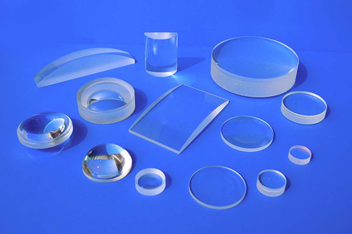
A custom fiber laser quartz end cap is typically cut from qualified fused silica, ground to OD and length, prepared at the splice end, polished at the output end, cleaned and inspected. It may then be fusion-spliced with CO₂-laser or other suitable equipment and recoated or packaged as an assembly.
Keep responsibility clear: one supplier may deliver the optical blank while another performs the splice and final test. Acceptance criteria should identify the stage at which each dimension, surface and optical result is verified.
What a Useful End-Cap Specification Contains
Dimensions should be connected to optical operating data. Without wavelength, mode-field information, power and pulse conditions, a supplier can quote a shape but cannot judge whether the finish and coating direction are appropriate.
- Fiber type, core/cladding dimensions, NA or mode-field data
- Wavelength, average power, peak power, pulse duration and repetition rate
- End-cap material, OD, length and concentricity/datums
- Splice-end preparation and output-face angle/clocking
- Surface quality, clear aperture, flatness and AR coating
- Mounting, cooling, environment, cleanliness, packaging and quantity
Frequently Asked Questions
How does a quartz end cap reduce laser damage?
It gives the beam distance to expand in coreless fused silica before reaching the exposed surface, reducing irradiance at that interface. It also provides a larger, controllable surface for polish and coating.
How long should the end cap be?
Length depends on beam divergence, desired output diameter, package, alignment and splicing constraints. Optical propagation should be modelled with the actual fiber and wavelength.
Should the output face be angled?
Use an angled face when reflection steering is required and the system can accept beam deviation and clocking. A perpendicular face is simpler when axial output is the priority.
Is AR coating always required?
No. It depends on reflection budget, wavelength, angle and power. Where used, the coating must be designed and qualified for the actual laser conditions.
Can an end cap fix cladding-light problems?
It may change where power is distributed, but it is not a substitute for proper cladding-light management, splice design and thermal control in the complete laser system.
Related Quartz Glass Resources
- Custom Fiber Laser Quartz End Caps
- Optics and Laser Quartz Products
- Quartz Glass for Optics and Fiber Applications
- Custom Precision Quartz Components
Technical References
Specify the End Cap From the Laser Conditions
Send the fiber data, wavelength and power regime, desired output geometry, blank dimensions and finishing/coating requirements. We can review manufacturability of the fused-silica end-cap blank and inspection plan.