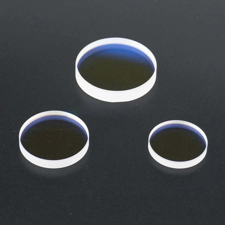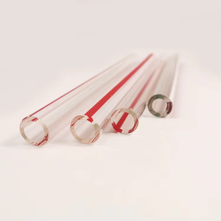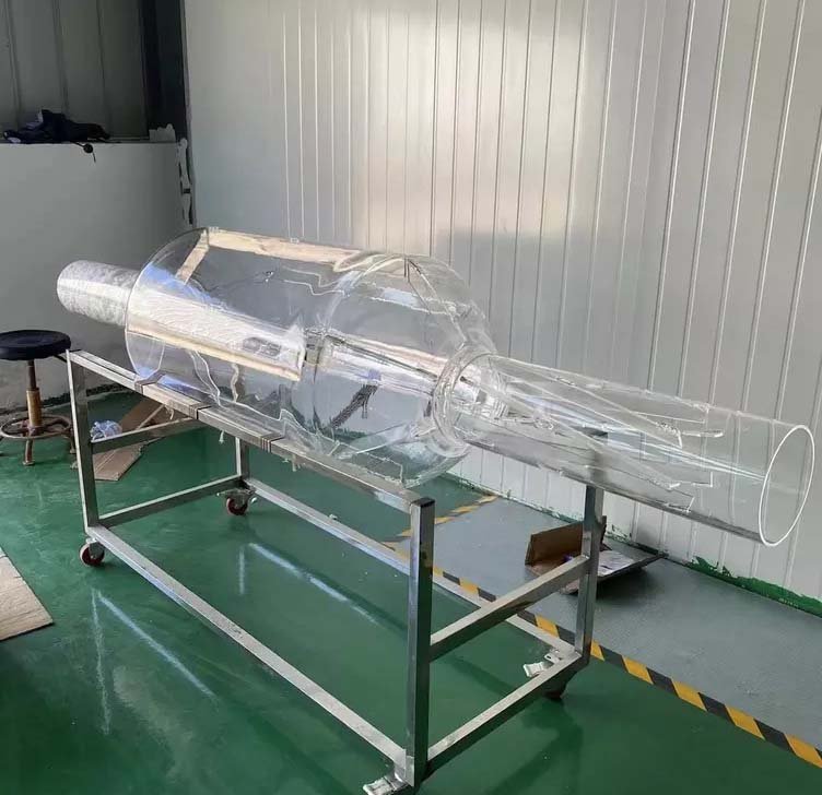
A quartz laser pump cavity is not just a transparent housing around a flashlamp and laser rod. Its bore locations, reflector geometry, coolant flow and spectral behaviour control how pump energy reaches the gain medium and how heat leaves the assembly.
A good specification separates the optical function from the mechanical envelope. Start with lamp, rod, pump spectrum and cooling architecture, then define quartz grade, bores, walls, finish, reflective treatment and interfaces.
Quick answer: Freeze the lamp and laser-rod centerlines first. Select an elliptical, circular or custom cavity around the intended coupling strategy, then define coolant passages, reflector type, quartz material and the surfaces that are polished, diffuse or coated. Tolerances should reference the optical axes, not an arbitrary outer face.
Key Takeaways
- Lamp-to-rod position and bore straightness are usually more important than cosmetic outer dimensions.
- Specular and diffuse reflector systems distribute pump light differently and need different surface preparation.
- Cooling channels must avoid stagnant zones and excessive wall thinning near critical bores.
- Material selection depends on UV exposure, solarization, fluorescence, purity and thermal load.
- A sample build should be evaluated in the real optical and thermal assembly before volume release.
What the Pump Cavity Has to Do
The cavity positions the pump source relative to the gain medium, redirects otherwise lost radiation, isolates or directs coolant and survives repeated optical and thermal loading. These functions interact: moving a coolant bore may improve flow but change reflector thickness or lamp-to-rod distance.
The design should identify the gain medium, lamp type, number of lamps, pumped length and target mode of operation. Continuous, long-pulse and flashlamp-pumped systems impose different average and peak thermal loads.
Elliptical, Circular and Custom Geometries
An elliptical cavity can place a lamp and rod near the two focal lines so reflected rays are directed between them. Circular and close-coupled geometries can be simpler and compact. Multi-lamp or noncircular arrangements may be chosen for power scaling or packaging.
Real cavities depart from ideal ray geometry because lamps and rods have finite diameter, reflectors are imperfect, coolant changes refractive conditions and apertures interrupt the surface. Optical modelling should use actual cross-sections and material interfaces rather than relying on the word “elliptical.”
| Geometry | Useful when | Specification focus |
|---|---|---|
| Elliptical | Lamp and rod coupling through focal geometry | Focal spacing, bore axes and reflector contour |
| Circular/coaxial | Compact close coupling | Concentricity and annular cooling |
| Multi-lamp | Higher pump power or tailored distribution | Axis pattern, symmetry and flow balance |
| Custom machined | Restricted envelope or special coolant path | Minimum walls, radii and inspection datums |
Reflector Systems and Surface Finish
A specular reflector preserves ray direction and depends on contour accuracy and smoothness. A diffuse reflector scatters pump light and can improve distribution in some architectures. Metal coatings, external reflector sleeves and diffuse ceramic systems each have different spectral, thermal and durability behaviour.
Do not call every internal surface “optical polish.” Mark polished transmission zones, diffuse reflector-support zones, sealed or coated surfaces and non-optical mounting faces. If a coating is required, specify spectral band, reflectance target, protected area, masking boundaries and coolant compatibility.
| Surface function | Typical finish direction | Control |
|---|---|---|
| Lamp/rod bore | Smooth transparent surface | Diameter, straightness and defects |
| Specular reflector interface | Polished/form-controlled | Contour and roughness |
| Diffuse reflector zone | Controlled matte/diffuse | Uniformity and boundaries |
| Bond/seal land | Process-specific finish | Width, flatness and cleanliness |
| Outer mount | Ground or machined | Datum position and edge condition |
Cooling Passages and Thermal Management
Coolant removes heat from the lamp, rod and cavity. Define inlet/outlet orientation, flow direction, fluid chemistry, pressure and temperature. Abrupt dead ends, narrow gaps and asymmetric paths can create local hot regions. At the same time, enlarging a passage can leave an unacceptably thin quartz web.
Thermal review should include lamp start-up, pulse repetition, fouling and loss-of-flow cases where relevant. Quartz has low expansion, but local temperature gradients and restrained seals still create stress. Avoid sharp internal corners and blend transitions between thick and thin sections.
Fused Quartz or Synthetic Fused Silica?
General fused quartz can suit many visible and near-IR pump systems. Synthetic fused silica may be selected for deep-UV exposure, low fluorescence, low contamination or tightly controlled optical behaviour. UV solarization resistance and hydroxyl content are grade-specific; they should not be inferred from a generic material name.
Use a traceable material callout where optical lifetime is critical. The materials collection and quartz optics guide help separate these grade decisions from the component geometry.
Manufacturing Route and Inspection
A custom quartz laser pump cavity may combine drilled or ground bores, CNC-machined outer contours, lapping, polishing, local frosting, quartz welding, coating preparation and final cleaning. The sequence matters because a later hot-working step can change a previously finished bore or datum.
Inspection should report the relationships that drive alignment: bore diameter and straightness, center distance, concentricity or position from optical datums, wall thickness, contour and seal-face geometry. Functional optical or flow tests may be more informative than tightening every cosmetic dimension.
Design Review Inputs
Provide a section through the lamp and rod axes plus the complete coolant circuit. Mark surfaces by function and separate reference geometry from acceptance-critical dimensions.
- Gain medium, lamp type, pumped length and operating mode
- Centerlines, bore diameters, minimum walls and outer envelope
- Reflector type, spectral band, coating or diffuse treatment
- Coolant, flow, pressure, temperatures and port geometry
- Material grade, UV lifetime, fluorescence and purity requirements
- Alignment datums, surface finish, cleaning, test and quantity
Frequently Asked Questions
Why is fused quartz used in laser pump cavities?
It combines useful optical transmission, high-temperature capability, low expansion and the ability to be machined, polished and hot-worked into multi-bore or coolant-handling components.
Is an elliptical cavity always most efficient?
No. Efficiency depends on finite lamp and rod geometry, reflector behaviour, coolant and packaging. Elliptical focal geometry is one option, not a universal answer.
Should pump-cavity bores be polished?
Bores that transmit pump light usually need a controlled smooth finish, but other zones may be intentionally diffuse or non-optical. Assign finish by surface function.
Can the reflector be coated directly on quartz?
Some systems use coatings or reflective layers, while others use an external sleeve or separate reflector. Spectral, thermal, adhesion and coolant requirements determine suitability.
What should be prototyped first?
Verify bore alignment, assembly fit, coolant flow and pump uniformity in the real system before refining noncritical cosmetic details or releasing a production quantity.
Related Quartz Glass Resources
- Custom Quartz Laser Pump Cavities
- Optics and Laser Quartz Products
- Quartz Glass for Optics and Fiber Applications
- Custom Precision Quartz Components
Technical References
Build the Cavity Around the Optical Axes
Send the lamp and gain-medium geometry, coolant circuit, reflector concept and surface map. We can review bore relationships, minimum walls, machining and finishing sequence for a custom quartz cavity.