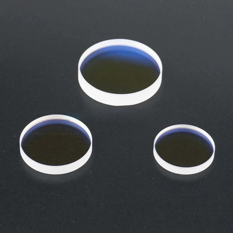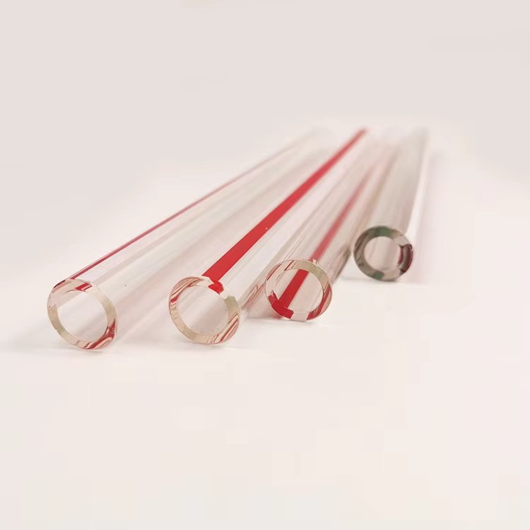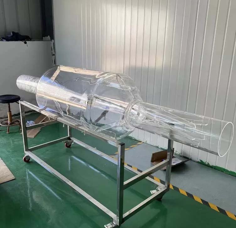
A quartz light guide rod transports light by total internal reflection, but real performance is decided at the interfaces. Launch angle, end-face polish, side-surface quality, bends, tapers, mounting contact and contamination all determine how much useful light reaches the target.
The specification should begin with source, wavelength and required output—not with a stock rod diameter. From there, geometry and finishing can be selected to preserve, reshape or deliberately diffuse the beam.
Quick answer: Use polished, parallel end faces and a smooth sidewall when the goal is efficient transport. Add a controlled taper to change beam size or irradiance, a bend to route the path, or a frosted section to extract light. Define every optical and mechanical zone on the drawing because one uniform finish rarely serves the whole part.
Key Takeaways
- Source wavelength and launch numerical aperture determine the usable material and acceptance cone.
- End-face flatness, angle and polish control coupling loss and beam deviation.
- Sidewalls should be optical-smooth for transport or intentionally textured for diffusion—not accidentally between the two.
- Bend radius, taper angle and cross-section transitions affect ray retention and local irradiance.
- Mounts must avoid scratching the optical sidewall or stripping guided rays through unwanted contact.
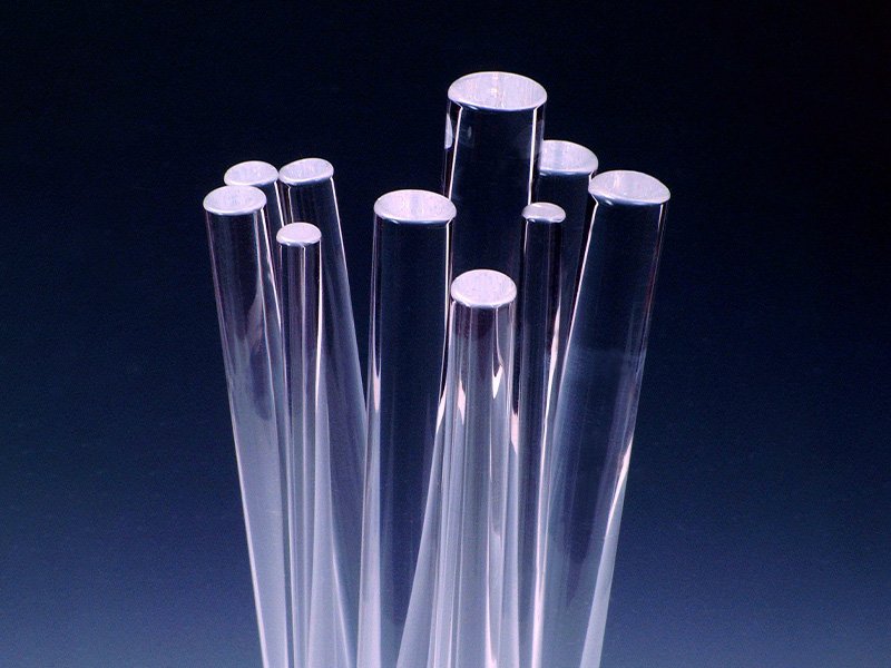
How a Quartz Light Guide Works
Light entering within the guide's acceptance range reflects from the quartz-air boundary when the internal incidence angle exceeds the critical angle. Each reflection keeps the ray inside the rod until it reaches an end face, a bend that violates the condition, a damaged region or an extraction surface designed to scatter it out.
The simple explanation assumes a clean quartz-air interface. Adhesives, metal contact, liquids or contamination around the sidewall change the boundary and can create local leakage. Mechanical design is therefore part of the optical design.
Material Selection by Wavelength and Environment
Natural fused quartz works for many visible, near-UV and thermal-light applications. Synthetic fused silica is preferred when deep-UV transmission, low fluorescence, very low contamination or tighter optical homogeneity is required. Hydroxyl content becomes relevant for infrared bands, so “quartz” alone is not a sufficient material callout.
Also state the operating environment. High temperature, UV exposure, radiation, vacuum, humidity, aggressive chemistry and repeated cleaning can change the acceptable material, coating and mounting method. The quartz optics and fiber buying guide gives a broader material overview.
| Application need | Material/finish direction | Critical confirmation |
|---|---|---|
| Visible illumination | General optical fused quartz; polished ends | Coupling geometry and sidewall finish |
| Deep-UV delivery | UV-grade synthetic fused silica | Transmission, fluorescence and contamination |
| Near-IR delivery | Low-OH grade where absorption matters | Actual spectral band and path length |
| High-power laser | Qualified fused silica and low-defect polished faces | Power density, pulse parameters and coating |
| Diffuse line/light extraction | Controlled ground or frosted extraction zone | Uniformity along the active length |
End Faces: Coupling Efficiency Starts Here
A nominally square-cut end can still steer the beam if angular error is large relative to the system. Specify end-face angle to the rod axis, flatness where required, surface quality and edge condition. A small protective chamfer reduces chipping but must stay outside the clear aperture.
For high-power or low-loss use, request inspection of chips, scratches and subsurface damage, plus an appropriate cleaning and packaging method. Anti-reflection coatings may reduce Fresnel loss, but coating band, angle, fluence and environmental durability must be defined.
| End-face feature | Optical effect | Drawing callout |
|---|---|---|
| Perpendicularity | Beam pointing and coupling alignment | Angle to mechanical datum |
| Flatness | Wavefront and contact/coupling behaviour | Clear-aperture flatness only if needed |
| Surface quality | Scatter and damage initiation | Scratch-dig or agreed defect criteria |
| Chamfer | Chip protection | Width/angle outside optical aperture |
| AR coating | Lower interface reflection | Wavelength, AOI, polarization and damage requirement |
Straight, Bent and Tapered Light Guides
A straight cylindrical rod is the easiest geometry to polish, inspect and align. Bends route light around equipment, but small radii allow more rays to escape and make surface quality around the bend important. Specify centerline radius, bend angle, leg lengths, plane of bend and allowed twist.
A taper changes cross-section and redistributes angles. It can enlarge or reduce the output spot, but conservation of optical étendue limits what passive geometry can achieve. Smooth transition, taper angle and end diameters should be evaluated with the real source distribution—not a single ideal ray.
Transport Surface vs Diffusing Surface
For efficient transport, the sidewall should be smooth and protected from contact that couples light out. For a side-emitting guide, a selected zone can be frosted, ground, laser-textured or patterned so light leaves progressively. Uniform side emission usually needs a changing extraction density rather than one constant roughness over the full length.
Mark transport, extraction, mounting and masked zones separately. If the design needs a reflective backing or metal sleeve, show its position and gap; direct contact can alter the optical boundary.
Manufacturing and Optical Finishing Options
Custom quartz light guide rods can combine precision cutting, centerless or cylindrical grinding, end-face lapping and polishing, side polishing, local frosting, bending, tapering, fire polishing and joining. Not every operation should be applied to every surface; a fabrication map avoids unnecessary cost and contradictory requirements.
Inspection can include diameter, straightness, bend geometry, end angle, visual defect limits, transmitted-light observation and application-specific optical checks. Define acceptance around the function—for example output uniformity or coupling loss—when conventional cosmetic criteria alone do not predict performance.
- Separate optical zones from mounting and handling zones.
- Dimension bends from a centerline and provide a clocking datum.
- State whether diameter tolerance applies before or after polishing.
- For tapers, define both end diameters, transition length and straight sections.
- Identify coating, masking, frosting and cleanliness boundaries.
A Functional Specification Checklist
The strongest RFQ describes both light and hardware. Include source type, wavelength band, optical power or pulse data, input numerical aperture, target output and available mechanical envelope. Add a drawing that locates every surface treatment.
- Material grade and wavelength range
- Input/output diameter, length, taper and bend geometry
- End-face polish, angle, flatness and clear aperture
- Sidewall transport, extraction, frosted and mounting zones
- Coating, power density, pulse duration and repetition rate where applicable
- Mounting, environment, cleaning, inspection and quantity
Frequently Asked Questions
Is a quartz light guide the same as an optical fiber?
Both use internal reflection, but a rigid rod is usually much larger, has different confinement and is integrated as a machined component rather than a flexible cable. The launch and mounting conditions differ.
Should the side surface be polished?
Polish or a very smooth as-drawn surface supports efficient transport. A controlled rough surface is useful only where intentional side emission or homogenization is required.
How small can the bend radius be?
There is no universal minimum. It depends on diameter, numerical aperture, refractive boundary, source distribution, fabrication method and acceptable loss. Model and prototype the actual geometry.
Does a taper concentrate light?
A taper can change beam area and angular distribution, but it cannot violate conservation of étendue. Higher irradiance may come with increased divergence or loss.
What causes unexpected dark or bright zones?
Common causes are surface contamination, clamp contact, inconsistent frosting, bend loss, source misalignment and local diameter or surface changes.
Related Quartz Glass Resources
- Custom Quartz Light Guide Rods
- Quartz Glass for Optics and Fiber Applications
- Custom Precision Quartz Components
- Optics and Laser Quartz Products
Technical References
Define the Optical Zones Before Choosing the Finish
Send the source wavelength and NA, target output, mechanical envelope and a marked-up drawing of polished, frosted, coated and mounting zones. We can review the manufacturable rod geometry and finishing sequence.