Quartz flange design is a coordination problem between a brittle glass part and a usually metal assembly. The bolt circle may be easy to calculate, but hole edge distance, sealing width, washer contact, tube-to-flange transition and differential expansion determine whether the flange survives installation and temperature cycling.
The drawing should define the pattern unambiguously from datums and avoid transferring bolt torque directly into the quartz. A strong design treats the metal retainer, gasket and quartz flange as one load path.
Quick answer: Specify flange OD, bore, thickness, pitch-circle diameter, hole count, hole diameter and start angle from a named datum. Provide adequate edge distance and sealing land, use a compliant gasket and broad load-spreading hardware, and allow quartz-to-metal thermal movement. Do not tighten bolts directly against bare quartz as if it were a steel flange.
Key Takeaways
- PCD plus hole count is incomplete without start angle or a clocking datum.
- Hole position should be toleranced as a pattern relative to the bore or tube axis.
- Bolt preload must be distributed through gaskets, sleeves, bushings or retainers—not concentrated at hole edges.
- The sealing land needs its own flatness and surface-finish requirement.
- Welded tube transitions and metal-frame expansion should be reviewed before thickness is finalized.

Define the Bolt Circle Without Ambiguity
Pitch-circle diameter is the diameter of the circle passing through all hole centres. For an equally spaced pattern, angular spacing is 360 degrees divided by the number of holes. A start angle locates the first hole relative to an axis or datum; without it, the pattern can rotate and interfere with ports or equipment.
Coordinate data can be generated from PCD, hole count and start angle, but the manufacturing drawing should still identify the controlling geometry. Our Quartz Flange Hole Pattern Calculator outputs angular spacing and X/Y centres for checking CAD or inspection data.
PCD Coordinates and Pattern Tolerancing
For a hole at angle θ on a bolt circle, its nominal center coordinates are X = (PCD/2) cos θ and Y = (PCD/2) sin θ relative to the pattern origin. Subsequent holes add the equal angular spacing. Coordinate lists are convenient for programming and checking, but separate plus/minus tolerances on X and Y can create a square acceptance zone that is hard to interpret.
Where drawing practice allows, position tolerance relative to the central bore and a clocking datum communicates pattern function more directly. Also define whether the hole is drilled, ground, slotted or fire-polished and which diameter represents final acceptance.
| Pattern input | Purpose | Common omission |
|---|---|---|
| PCD | Sets radial position of hole centres | Confusing radius with diameter |
| Hole count | Sets equal angular spacing | Assuming every pattern is equally spaced |
| Start angle | Clocks the pattern | No datum direction |
| Hole diameter | Provides clearance or bushing fit | Ignoring final edge finish |
| Position tolerance | Controls assembly fit | Tolerancing holes from flange OD instead of functional bore |
Edge Distance, Hole Finish and Local Stress
A hole removes load-carrying section and introduces a stress concentration. Keep adequate ligament between the hole and outer edge, central bore, neighbouring holes and welded transitions. The required distance depends on load and geometry, so a simple one-diameter rule should not be treated as a universal design code.
Control chips and microcracks at both hole entrances. Specify chamfer or edge break and avoid sharp countersinks unless they are necessary and reviewed. Metal bolts should not bear directly against uneven quartz hole edges; use suitable sleeves, bushings, washers or a separate clamp ring.
Design the Sealing Land Separately
The sealing face has different requirements from the rest of the flange. Define gasket type, contact width, compression, fluid, vacuum/pressure and temperature. Then specify local flatness and finish over that annular land rather than over-polishing the entire flange.
Keep holes and chips away from the sealing path. If a tube is welded close to the land, allow for distortion and plan the finishing sequence so the final face is inspected after hot work. For vacuum use, identify leak-test method and acceptable rate at assembly level.
| Seal concept | Benefit | Quartz-specific concern |
|---|---|---|
| Elastomer O-ring | Compliance and reusable assembly | Groove/land geometry, temperature and chemistry |
| Flat gasket | Broad load distribution | Compression uniformity and extrusion |
| Bonded seal | Compact permanent interface | CTE mismatch, cure shrinkage and outgassing |
| Metal retainer over gasket | Keeps bolt load off quartz | Flatness, alignment and torque sequence |
Tube-to-Flange Transition and Fabrication
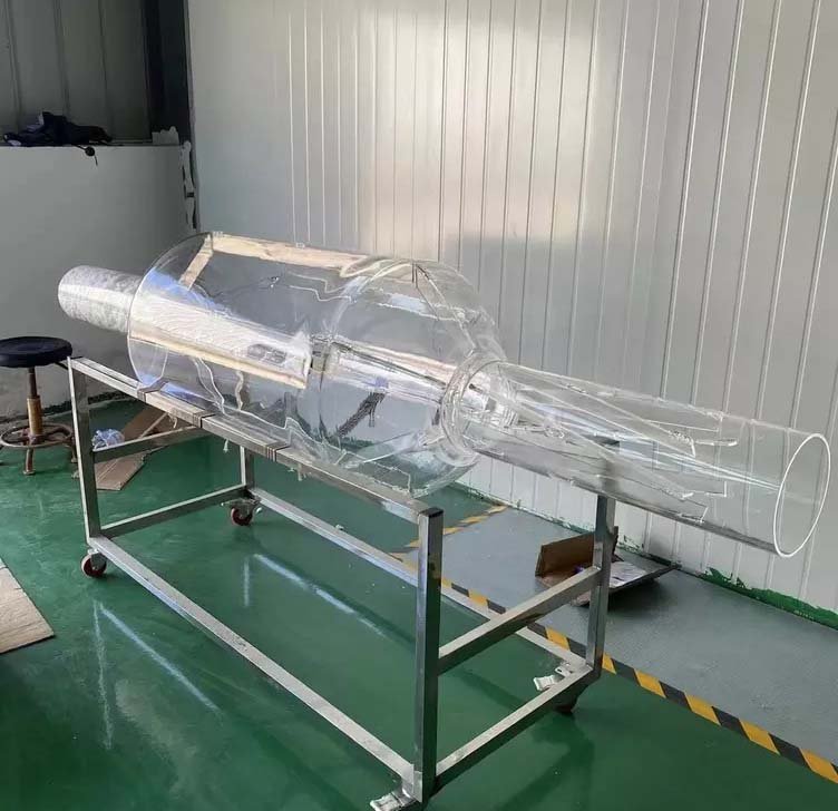
A custom quartz flange may be machined from plate or formed and welded to a tube. The transition should avoid an abrupt thick-to-thin step and sharp re-entrant corners. A gradual blend distributes thermal and mechanical strain more effectively.
Manufacturing can include blank cutting, core drilling, bolt-hole drilling/grinding, face lapping or polishing, edge finishing, tube alignment, quartz welding, annealing and final inspection. Dimension critical faces after the process step most likely to move them.
- Use the tube or bore axis as a functional datum where possible.
- Show minimum remaining wall at the welded transition.
- Separate cosmetic finish from sealing and alignment surfaces.
- Define hole edge condition and allowed chips on both faces.
- Inspect PCD, flatness and runout after final hot work.
Thermal Movement and Mounting Hardware
Quartz expands far less than common stainless steels and aluminium alloys. A metal bolt circle can move radially outward while the quartz pattern barely changes, loading the hole edges if the clearance and bushings are too tight. Slots, oversized clearance holes, floating retainers or compliant elements may be needed depending on temperature.
Calculate differential movement at the actual flange temperature using the Differential Thermal Expansion Calculator. Then review contact stress and gasket travel; movement alone does not prove the joint is safe.
Complete Flange RFQ Checklist
Provide the mating metal flange or equipment drawing so hole pattern, gasket and clearances can be checked together. Mark the load direction and state whether the quartz part carries pressure, vacuum or only a protective cover.
- Flange OD, bore, thickness, flatness and surface finish
- PCD, hole count, diameter, start angle and position tolerance
- Tube size, axis, welded transition and minimum wall
- Gasket/retainer details, bolt hardware and tightening method
- Temperature profile, pressure/vacuum, chemistry and cycles
- Material grade, inspection, leak test, cleaning and quantity
Frequently Asked Questions
What is PCD on a quartz flange?
Pitch-circle diameter is the diameter of the circle passing through the hole centres. It must be combined with hole count, start angle and a datum to define the pattern.
Can bolts clamp directly onto quartz?
Direct concentrated bolt load is risky. Use an engineered retainer, gasket and load-spreading hardware so preload is distributed and hard point contact is avoided.
Should flange holes be countersunk?
Only when the assembly truly requires it and the local thickness and edge condition are reviewed. A sharp countersink can increase stress concentration.
How do I allow for metal-to-quartz expansion?
Calculate radial and axial differential movement at operating temperatures, then provide clearance or compliance through the retainer, holes, bushings, slots or gasket system.
Can a quartz flange be welded to a large tube?
Yes for many geometries, subject to diameter, wall, transition and handling limits. The weld and sealing face should be designed and inspected as a connected structure.
Related Quartz Glass Resources
- Custom Quartz Flanges
- Custom Quartz Components
- Quartz Thermal Expansion Guide
- Quartz Glass Engineering Calculators
Technical References
Send the Mating Flange With the Quartz Drawing
Provide the metal mating interface, gasket concept, PCD data, operating temperatures and load cases. We can review the manufacturable quartz geometry, hole pattern, sealing land and tube-to-flange transition.