 Custom Low-OH Quartz Capillaries
Custom Fiber Optic Quartz Capillaries
| Parameter | Typical Range |
|---|---|
| OD | 0.3–3 mm |
| ID (bore) | 125 µm fiber-alignment option: bore selected above the actual fiber OD by drawing; larger component/bundle reference bores 0.25–1.5 mm |
| Bore tolerance | 125 µm fiber-alignment option: ±1–2 µm by agreed geometry; larger-bore reference: ±5–10 µm, subject to size and length review |
| Concentricity (bore-to-OD) | 125 µm fiber-alignment option: ≤2 µm by agreed geometry and inspection; larger bores specified separately |
| Recommended bore clearance | Specify minimum/maximum diametral clearance from actual fiber OD, its tolerance, insertion length and adhesive requirement |
| Length | 5–50 mm |
| End-face finish | Flat-cut, polished, or flared |

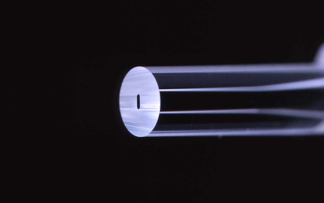
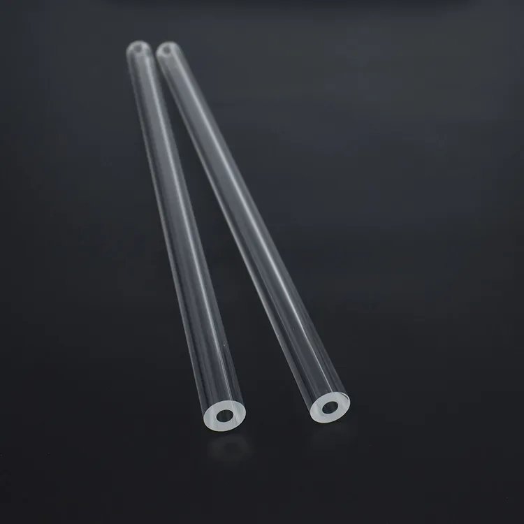
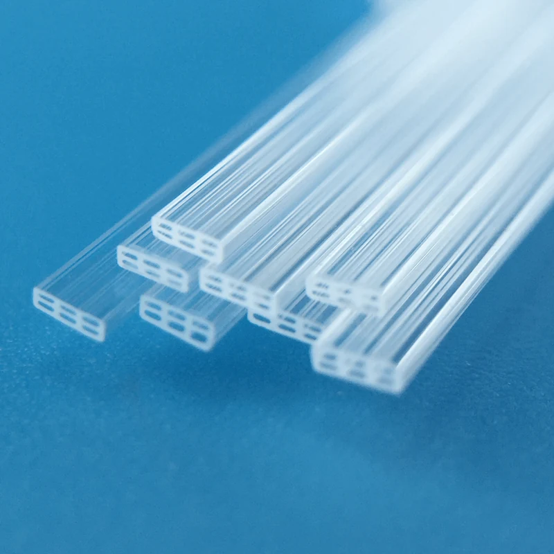
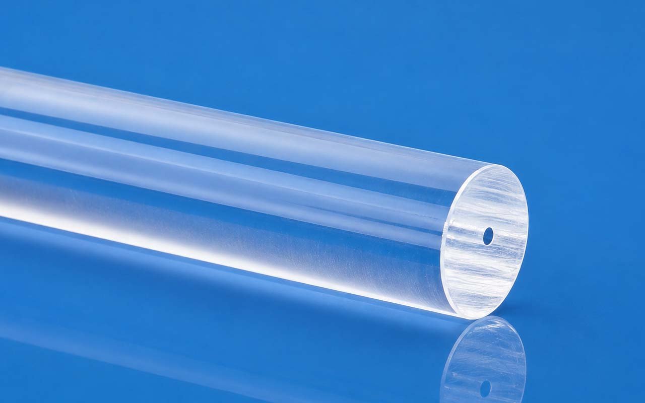
Fiber optic quartz capillaries locate a fiber or fiber bundle within a controlled bore for alignment sleeves, optical feedthroughs and end-cap interfaces. Select the bore from the actual fiber diameter and assembly clearance, then define how that bore must align with the outside mounting surface.
Bore Clearance for 125 µm Fiber
State whether the fiber is bare, coated or stripped over the insertion length. A nominal 125 µm cladding diameter is not the finished bore specification: minimum diametral clearance is the minimum capillary ID minus the maximum actual fiber OD. Allow for fiber tolerance, adhesive space and insertion length; do not assume a nominal 125 µm bore provides a slip fit.
Concentricity vs. Bore Tolerance
Bore tolerance controls the size of the passage; bore-to-OD concentricity controls its position when the outside is used as the mounting datum. For the 125 µm fiber-alignment option, the listed ±1–2 µm ID and ≤2 µm concentricity requirements must be agreed for the complete OD and finished length. The larger-bore reference tolerance of ±5–10 µm applies to a separate component/bundle series, rather than to that alignment option.
Fiber Entry and End-Face Options
A chamfer or flared entry helps thread the fiber without changing the specified working bore. Identify the lead-in length, insertion direction and the end face used as the axial datum. Ground, optically polished and fire-polished ends serve different functions; specify the required face quality and keep the entry free of chips or deformation that could damage the fiber.
Fit Starts with the Fiber
Specify Bore Clearance Before OD and Length
| Controlled Feature | What to Put on the Drawing |
|---|---|
| Fiber / Component OD | Nominal diameter and its toleranceThe capillary bore is selected from the actual mating component, not from a generic tube size |
| Finished Bore ID | Fiber OD plus the required insertion, adhesive or thermal-expansion clearance |
| ID Tolerance | 125 µm fiber-alignment option: ±1–2 µm by agreed geometry. Larger component/bundle bores: reference ±5–10 µm, reviewed by ID, OD, finished length and inspection method. |
| Outer Diameter / Profile | Round OD or a drawing-specific outer datum for the holder |
| Concentricity | 125 µm fiber-alignment option: ≤2 µm by agreed geometry and inspection; larger bores specified from the OD or functional outer datum |
| Taper | Maximum permitted ID change over the working length where fiber alignment depends on it |
| Finished Length | Cut length with the end-face datum identified |
| End Geometry | As-cut / ground square / polished / chamfered / flared entry |
Bore Selection
Common IDs for Fiber and Component Alignment
| Reference Bore ID | Typical Mating Element | Quote-Critical Detail |
|---|---|---|
| 125 µm fiber-alignment option | Bare-fiber alignment, with finished bore selected above actual fiber OD | Actual element OD, insertion clearance and finished length |
| 0.25 / 0.30 mm | Coated fiber, small optical element or sensor lead | Coating condition and whether adhesive space is required |
| 0.50 / 0.80 mm | Fiber bundles, ferrules and compact feedthroughs | Bore centering and end-entry geometry |
| 1.0 / 1.5 mm | Larger optical elements and protected transitions | OD fit, wall section and end-face finish |
Interface Options
End Geometry That Protects the Fiber During Assembly
Precision Round BoreCentered channel for repeat fiber position inside a round OD
Flared Fiber EntryLead-in geometry reduces edge contact during fiber insertion
Chamfered EndsDefined entry chamfer for assembly without a sharp bore edge
Ground or Polished FacesFinished ends for optical interfaces, bonding and controlled axial length
Applications
Where Bore Position Matters More Than Tube Size
Fiber Alignment & SplicingCentered sleeves and transitions that hold fibers on a repeat optical axis
Ferrules & Optical FeedthroughsQuartz interfaces for bonding, packaging and passage through instrument housings
Photonic & Medical ProbesSmall rigid guides where fiber clearance, entry geometry and finished length control assembly
Need a capillary matched to a fiber?Send fiber OD and tolerance, target bore clearance, capillary OD, finished length and end-face drawing.
Open the Capillary ConfiguratorEngineering Data
Grade-Qualified Material Purity
Electric-fused / flame-fused quartz: SiO₂ ≥99.99%; synthetic JGS1-grade fused silica: ≥99.999%. Grade and lot certificate govern supplied material.
Engineering Data
Related Quartz Parts for VAD, OVD and Fiber Drawing
Optical-fiber manufacturing components include quartz seed and support rods for VAD / OVD deposition, tail tubes, VAD connectors and sintering rings, isolation covers, draw-furnace sealing sleeves, quartz gaskets and pressure-ring tail seals. Support rods · Sealing sleeves · Sintering and pressure rings. These are process fixtures specified by drawing, separate from the precision capillary bore series.
Customize This Product
Enter your dimensions of Custom Fiber Optic Quartz Capillaries — the technical drawing updates instantly, then request a quotation.
Technical Drawing
Drawing redraws live · blue hatched area = cut section · all dimensions in mm
Parameters
Every field is editable — drawing, weight estimate and part code update instantly.
Common Options
pcs
Configuration Summary
Attached to your inquiry automatically when you press “Use This Configuration”.
—