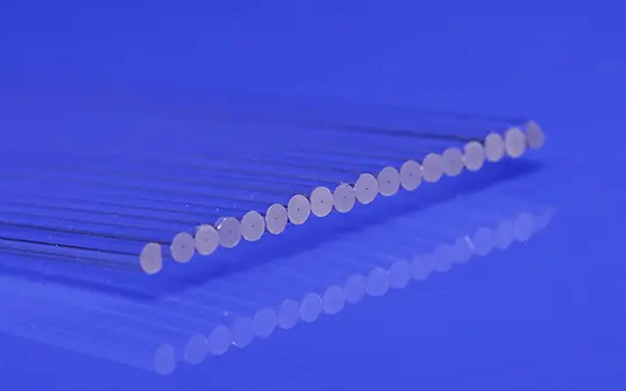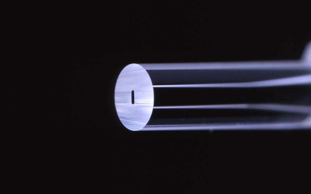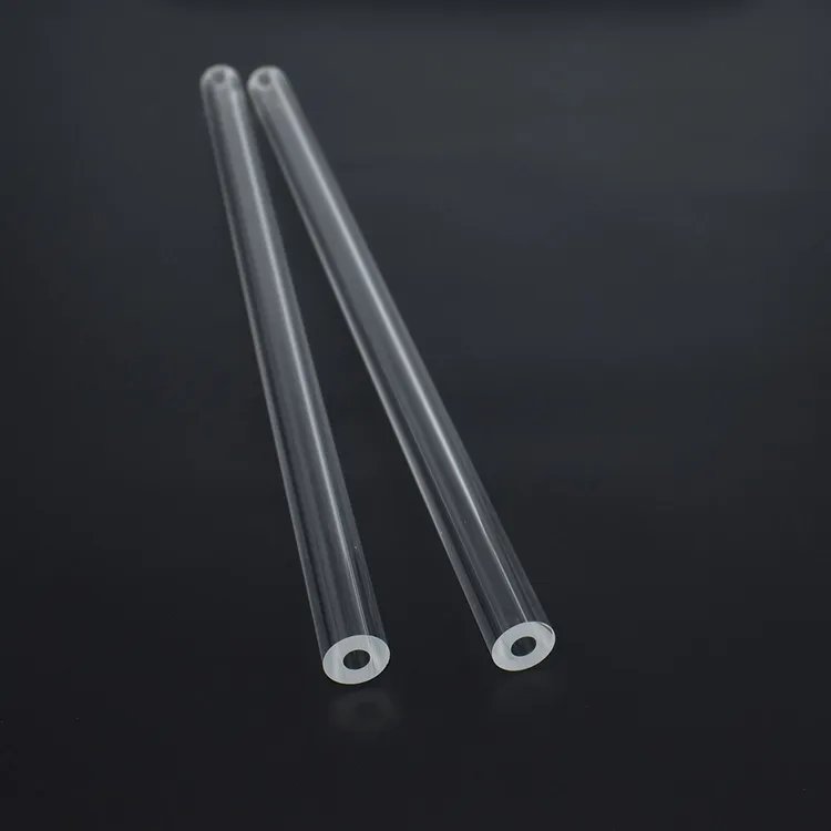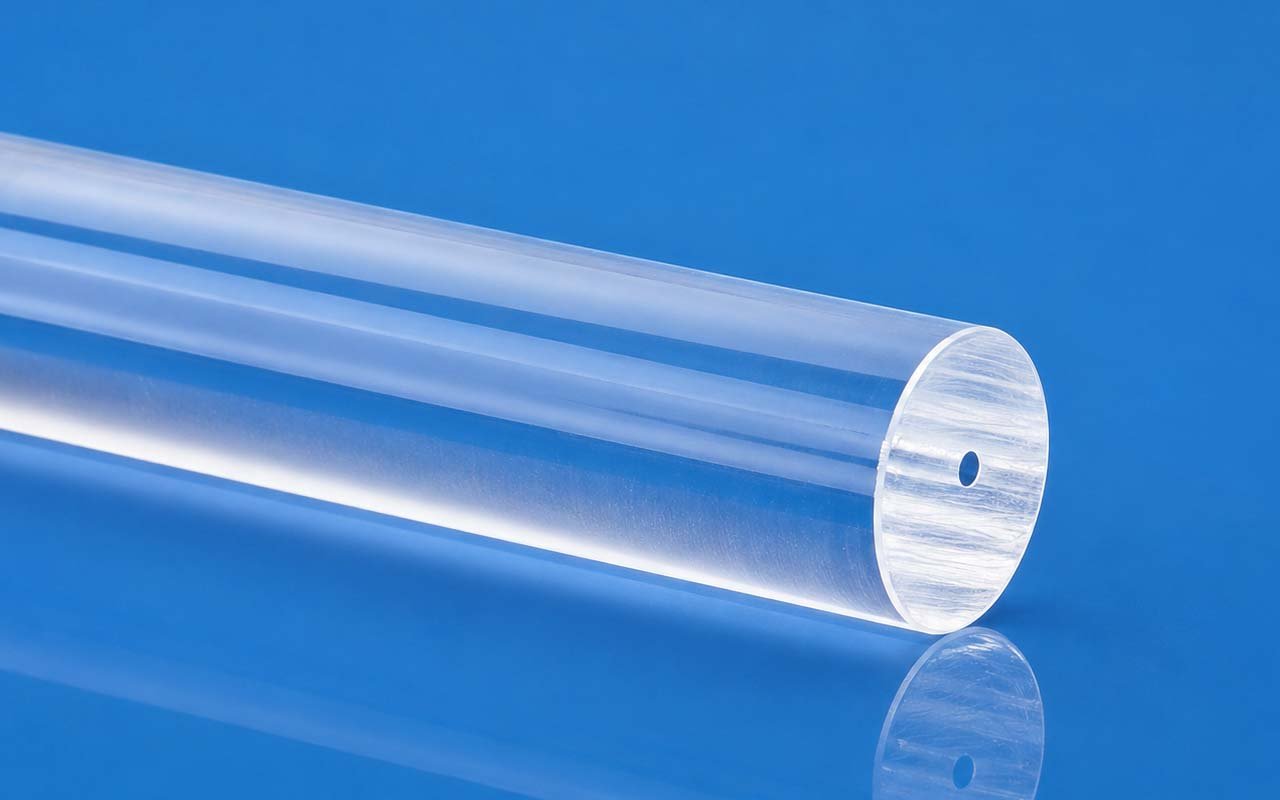
 Custom Fiber Optic Quartz Capillaries
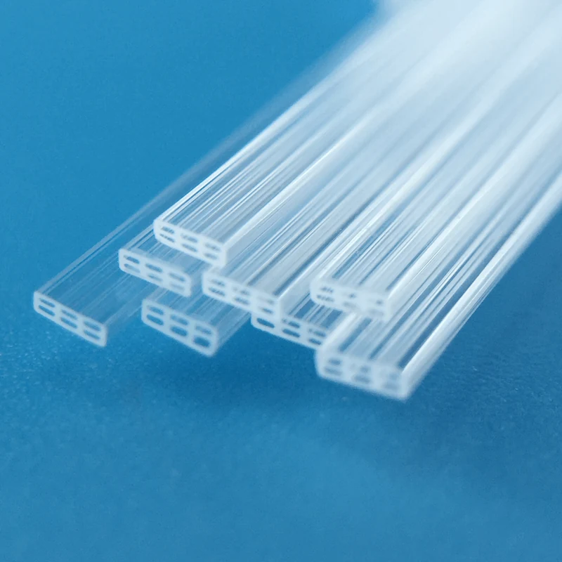
Custom Multi-Hole Quartz Capillaries
| Parameter | Factory Standard | Manufacturing Limit |
|---|---|---|
| OD | 0.5–10 mm | — |
| Hole count | 2–7 | Up to 19, pattern-dependent |
| Bore diameter | 0.05–1 mm per hole | Tolerance-dependent below 0.1 mm |
| Hole pitch / PCD | 1.2–3× bore diameter | Tighter pitch narrows web thickness |
| Web thickness | ≥0.1 mm | Down to 0.05 mm on request |
| Hole position tolerance | ±0.01–0.02 mm | Tighter, confirmed per order |
| Length | 10–500 mm | — |
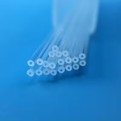
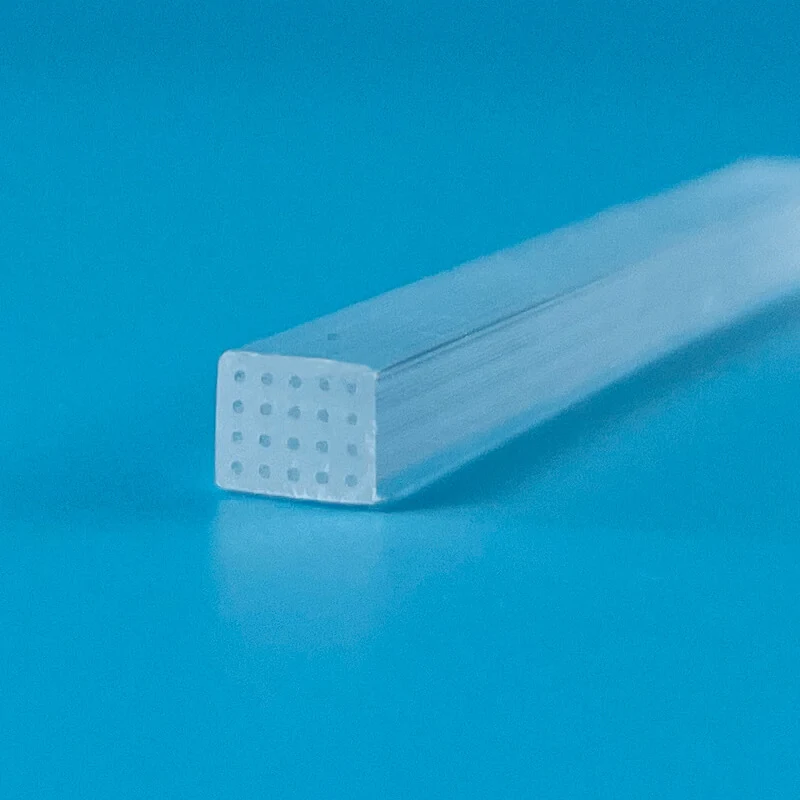
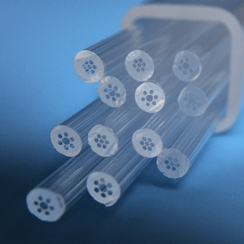
Multi-hole quartz capillaries combine several longitudinal channels in one dimensioned cross-section for fiber arrays, sensor routing and parallel fluid paths. Hole count, each bore size, spacing and the surrounding quartz section must be specified together.
Hole Pattern, Pitch and PCD
Provide an indexed end-view drawing showing every hole diameter and its center location. Use center-to-center pitch for an inline or rectangular array, or pitch-circle diameter for a ring pattern; identify any center hole separately. Mixed-diameter channels need individual labels, and a hole-count description alone cannot define the layout.
Minimum Web Thickness
The web is the quartz remaining between neighboring channels. Increasing a bore or reducing pitch reduces that section, while the distance to the outer surface sets the minimum outer wall. Dimension both limits and allow for bore-size and position tolerances. A nominally symmetric pattern still requires a minimum-section check across the complete cross-section.
Hole Position and Pattern Orientation
Distinguish the position of holes within the pattern from the position of the complete pattern relative to the outside datum. If a holder or connector fixes rotation, define an angular datum, reference face or orientation mark so the channels can be indexed during assembly. Specify finished length and verification that every channel remains open; the longitudinal drawn pattern should not be treated as a generic drilled-hole specification.
Cross-Section Control
Hole Diameter, Pitch and Web Must Be Drawn Together
| Controlled Feature | Reference Capability / Requirement |
|---|---|
| Hole Count | 2–7 longitudinal channels; 2 / 3 / 4 / 7 are reference layouts |
| Single-Hole ID | Diameter specified for every channel; mixed IDs require an indexed cross-section |
| Hole Tolerance | Reference ±0.01–0.03 mm according to hole size and layout |
| Pitch / PCD | Center-to-center spacing or pitch-circle diameter |
| Web Thickness | Minimum quartz section between adjacent holes |
| Outer OD / Profile | Round or drawing-specific outside datum |
| Hole Position | Located from the outer datum and an orientation mark where rotation matters |
| Length / Ends | Cut length with all channels open and visible at the finished faces |
Layout Selection
Use the Smallest Hole Count That Fits the Routing
| Layout | Geometry to Control | Typical Function |
|---|---|---|
| 2-hole parallel | Two IDs, pitch and web | Dual fluid paths, electrodes or paired fibers |
| 3-hole triangular / inline | Pattern orientation and pitch | Sensor bundles and compact multi-channel probes |
| 4-hole square | X/Y pitch and outer datum | Fiber or electrode arrays |
| 7-hole ring + center | PCD, center bore and six webs | Microreactors, distribution and multi-fiber assemblies |
Hole Layouts
Common Multi-Hole Cross-Sections
Two-HoleParallel channels with pitch and separating web controlled
Three-HoleInline or triangular pattern indexed to the outside profile
Four-HoleSquare array for fibers, electrodes or balanced flow paths
Seven-HoleCenter channel surrounded by six channels on a defined PCD
Applications
Multi-Channel Quartz Functions
Fiber ArraysSeveral fibers aligned in one stable quartz cross-section
Fluid DistributionParallel channels for sample, reagent, purge and reference flow
MicroreactorsDefined channel groups with controlled quartz webs for reaction and heat transfer
Sensor & Electrode ProbesIsolated paths for wires, electrodes and sensing elements
Need a custom multi-hole cross-section?Send hole count, each ID, pitch or PCD, minimum web, outer profile, orientation and length.
Open the Capillary ConfiguratorEngineering Data
Grade-Qualified Material Purity
Electric-fused / flame-fused quartz: SiO₂ ≥99.99%; synthetic JGS1-grade fused silica: ≥99.999%. Grade and lot certificate govern supplied material.
Customize This Product
Enter your dimensions of Custom Multi-Hole Quartz Capillaries — the technical drawing updates instantly, then request a quotation.
Technical Drawing
Drawing redraws live · blue hatched area = cut section · all dimensions in mm
Parameters
Every field is editable — drawing, weight estimate and part code update instantly.
Common Options
pcs
Configuration Summary
Attached to your inquiry automatically when you press “Use This Configuration”.
—