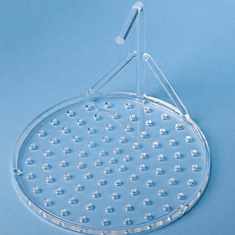
 Custom Quartz Cleaning Tanks
Custom Quartz Wafer Carriers & Holders
| Parameter | Typical Range |
|---|---|
| Wafer size | 100 mm (4″), 150 mm (6″), 200 mm (8″) — other sizes on request |
| Pocket / support diameter | Matched to wafer OD plus clearance |
| Support / slot pitch | Confirmed per equipment (multi-wafer carriers) |
| Support point geometry | 3-point, edge-ring, or full-pocket contact |
| Frame size | Confirmed per equipment envelope |
| Position / flatness | Confirmed per equipment tolerance |
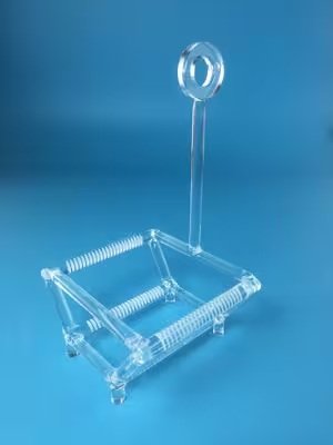
Quartz carriers and holders built around your wafer size and equipment interface — where the wafer contacts the part, and how the part sits in your equipment, are the specs that actually matter.
Wafer size, support geometry, and equipment envelope are one coupled set — a support point sized for the wafer OD still has to fit inside your equipment's available space, so send both together rather than wafer size alone.
Quartz Wafer Carriers & Holders for Semiconductor and Thermal Processing
Carriers and holders position one or more wafers for a specific process step — loading into a furnace, aligning under a process head, or holding a wafer during inspection. Which contact and support style fits depends on the process: a step that can't tolerate backside contact needs edge-only support, while a step needing more stability can use a full pocket.
Available Quartz Wafer Carriers & Holders Configurations
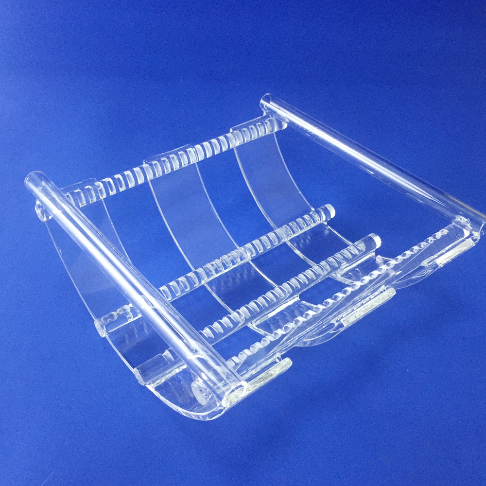
Single-wafer holders and multi-wafer carriers (cassette-style, with repeated slots) are both built on the same support principles. Tell us whether your application holds one wafer per part or several, since that changes whether pitch and slot count matter.
Wafer Support Points and Slot Geometry
Support point geometry determines contact area and particle risk — 3-point support minimizes contact but offers less stability, edge-ring support distributes contact around the wafer edge, and full-pocket support gives the most stability but the most contact area. Holes or pockets for support features are cut by mechanical or diamond drilling down to about Ø0.8 mm at ±0.02 mm, or by laser for finer features.
Quartz Wafer Carrier and Holder Designs
Frame size and handle geometry are set by how the part loads into and out of your equipment, not by wafer size alone — send your equipment model or a sketch of the loading mechanism if you have one. Fabrication is rod or plate stock machined for support features, then welded into the final frame; before shipment we check slot/support position, parallelism, overall dimensions, and weld points.
4–12 inWafer Formats
2.54 mmFine Pitch Reference
4.76 mmProcess Pitch Reference
10 mmWide Pitch Reference
3Core Structures
Low OHMaterial Option
Support Geometry
Locate Each Wafer from Functional Contact Points
| Controlled Feature | Reference Capability / Requirement |
|---|---|
| Supported Wafer | 4, 6, 8 or 12 inch; custom substrates by drawing |
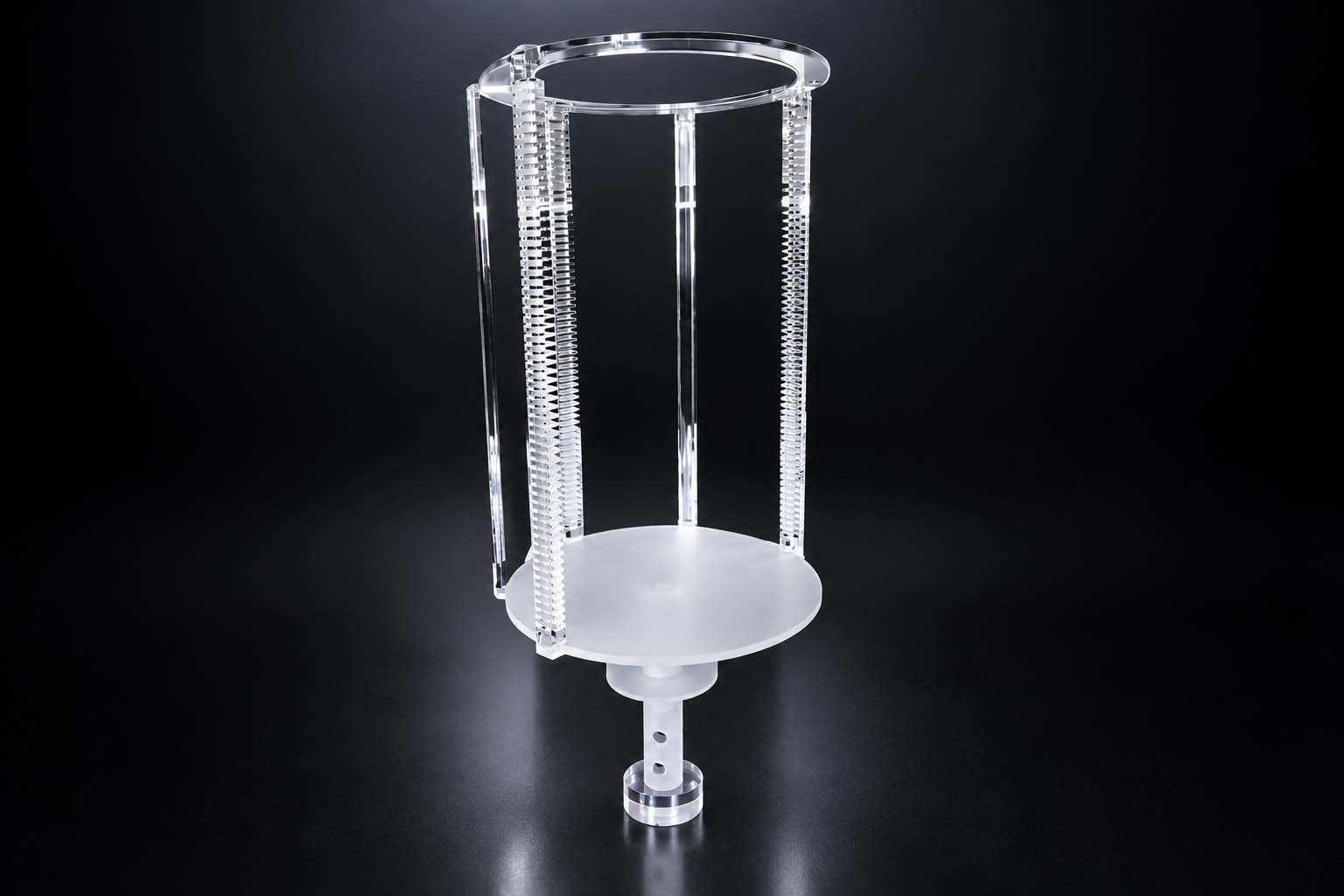
| Structure | Open basket, enclosed carrier or tray-style holder |
| Capacity | Defined from process batch size and equipment envelope |
| Slot / Support Pitch | 2.54, 4.76 or 10 mm reference series, or custom |
| Contact Geometry | Support points and edge clearance stated on the drawing |
| Handle / Transfer Interface | Fixed handle, removable interface or robot-compatible feature |
| Overall Envelope | Matched to the tank, furnace or transfer station |
| Material / Packaging | Low-OH quartz and clean packaging scope specified in the quotation |
Structure Selection
Choose the Carrier Around the Transfer Step
| Structure | Best Used When | Critical Drawing Inputs |
|---|---|---|
| Open carrier | Drainage and chemical access are primary | Wafer contact, pitch, handle |
| Box carrier | Protection during movement or storage is primary | Opening, cover and retention |
| Tray holder | Horizontal positioning is required | Support plane and pocket geometry |
| Custom frame | Existing equipment dictates the layout | Datums, envelope and transfer interface |
Available Forms
Configurations Defined by the Process
Open CarrierAccessible frame for wet-process circulation
Enclosed CarrierProtective support and retention geometry
Tray HolderHorizontal pockets or support points
Custom Transfer FrameEquipment-specific handle and locating features
Applications
Wafer Transport and Process Support
Wet CleaningOpen structures for chemistry circulation and drainage
Furnace LoadingQuartz supports matched to thermal-process equipment
Intermediate StorageDefined wafer contact and retention during handling
Equipment TransferCarrier geometry matched to manual or automated tooling
Product Examples
Product Forms and Finished Components
Need a carrier matched to process equipment?Send wafer size, capacity, pitch, contact geometry, overall envelope and transfer or handle details.
Open the Product ConfiguratorEngineering Data
Grade-Qualified Material Purity
Electric-fused / flame-fused quartz: SiO₂ ≥99.99%; synthetic JGS1-grade fused silica: ≥99.999%. Grade and lot certificate govern supplied material.
Holder compatibility with 4–12 in customer wafers describes the fixture envelope. It is separate from the quartz-wafer product line, whose standard manufactured wafer series is 25.4–150 mm (1–6 in). State wafer diameter, slot pitch and loading orientation on the fixture drawing.
Customize This Product
Enter your dimensions of Custom Quartz Wafer Carriers & Holders — the technical drawing updates instantly, then request a quotation.
Technical Drawing
Drawing redraws live · blue hatched area = cut section · all dimensions in mm
Parameters
Every field is editable — drawing, weight estimate and part code update instantly.
Common Options
pcs
Configuration Summary
Attached to your inquiry automatically when you press “Use This Configuration”.
—